


|
|
|
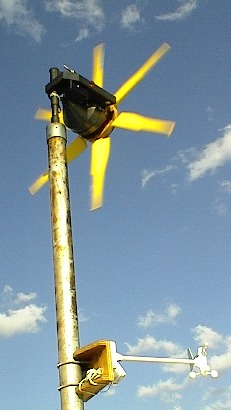
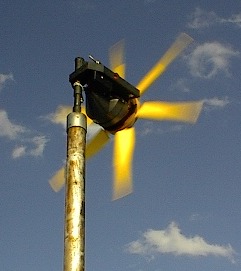
This is the second of a group of downwind turbines that I have been testing. This one has the identical alternator that the smaller one has with the exception of the magnets used.
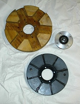
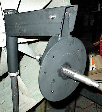
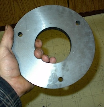
The next couple show the prop mount, bearing hub, and magnetic disc apart as well as assembled. There is a steel band around the magnetic disc to reduce the chances of the assembly coming apart at higher rpm. The magnets were mounted to a 8 inch x 1/4" thick steel disc and the band was welded to the edge. Magnets were epoxied into place then the gaps were filled with fiberglass resin.
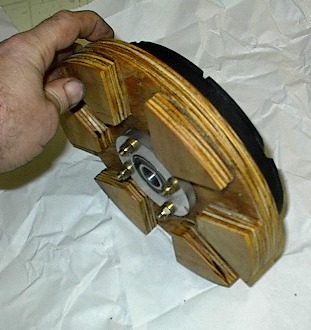
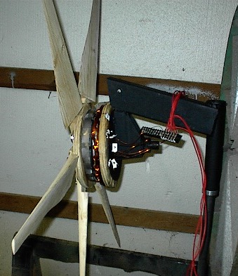
The 8 inch magnetic disc is mounted to a 9 1/4" x 3/4" plywood disc. The bearing hub and magnetic disc "sandwich" the plywood in place. I used 4- 1/4" aircraft bolts (AN hardware) along with the aircraft type nyloc nuts for safety reasons. Whether they are aircraft quality or not, I would recommend using the nyloc type nuts on any spinning assembly. The only difference between a standard grade 5 bold and an aircraft bolt is the aircraft bolts have been X-rayed for fractures, bubbles etc, and are guaranteed to be solid. Another note, on an aircraft these would also be safety wired into place leaving very little possibility of the assembly coming apart. The below picture shows it assembled ( first time up) in a jig in front of a large fan for initial testing.
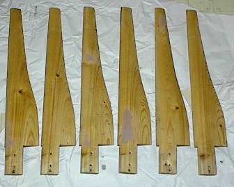
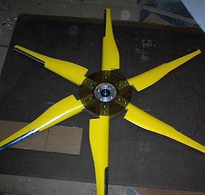
This one initially had a variable airgap system, star/delta switching, and full furling abilities. After the initial tests I'm undecided at this point if the variable air gap is worth the extra time and work. With the system working it will start spinning in about a 5 mph wind and start charging at around 7. With the system disabled it won't start spinning until around 10mph but instantly starts charging and once started will continue charging down to 7mph. So unless the wind drops below 5mph it will continue spinning.... I don't believe, at least for this unit, the variable air gap has done anything of any significance. The star/delta switch originally worked off the same system as the variable air gap and has had some problems in the switching stages causing a "chatter". Since I am utilizing the "torque" from the stator to activate it , the moment it switches it drops the torque load causing a back and forth movement until it stabilizes. This will be replaced with an electronic controller and retested. I will post results on this as it progresses. Here are some other shots of the blades and the completed rotor assembly....
They always look nicer with paint... although the finishing process isn't one of my favorite parts of the project it has to be done.... I placed 6 inch strips of leading edge tape on each blade. This helps to protect the edge when its spinning fast in the rain. The first few turbines I built didn't have this protection and the blades showed major erosion after about a year or so. Since then I've been using the leading edge tape you can get from ultralight aircraft suppliers with little to no problems with erosion. I balanced this one a little different than I've done in the past. I usually make a weight plate to bolt on the light side which has worked well in the past. This one, since the blades are small, I weighed each blade on a postal scale and matched all the other blades using small lead weights inset into the wood and epoxied in. Initial run up seems good but I've only had it to 800 rpm so far....that's running in a 12.5 mph wind with no load on it.... we'll see... Below shows the basic's of the stator mount, spindle and furling system. All the components of the furling system are not mounted in this shot but the basic gravity system is shown. Very similar to an automotive front spindle assembly... ( Look like a volvo?.....not quite, its all hand made - with tools of course). I wouldn't think it would take much to modify an automotive spindle to do the same job. If it can be done, the Dan's at www.otherpower.com will do it!!!
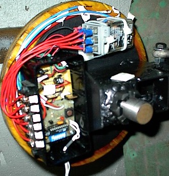
Below is a shot of the stator installed and the wiring almost completed.
I didn't really design it for all the electronics to fit behind the
cover so it became quite a challenge to get everything to fit. This is a star/delta
controller powered from the alternator itself to drive the relay. Bench testing
proved quite successful. The controller unit was designed and built by Robert Nance
Dee at The unit has since been completed and placed on the tower for some real life tests. Of course as soon as you put up a new unit mother nature has to play games with you and there has been little to no wind for a couple days now. But I did get some interesting results in the lower winds. The chart below shows the output that I've been able to collect so far....
The first thing I noticed that was outstanding from the upwind versions was the slower pivot when adjusting for variations in the wind direction. It seems to correct itself at a very even pace which would lead to less stress on the blades as well as the bearings. The second characteristic that stood out was the the way the rotor speed changed. The rotor actually came out fairly heavy with the steel disc, magnets, blades etc. and it seems to pick up rpm at a steady pace and also when the wind drops off it slows down much more slowly. Like a flywheel absorbing energy and bleeding it off as the power was relieved. The blades were designed to run at a TSR of 4 and I noticed it running below that in lower winds and above the rated mark in the moderate winds. There seems to be more load than the blades are making in power at the lower range but the blades are outperforming the alternator in the upper range. This could be caused by the core saturating to quickly or the ceramic magnets aren't saturating the coils properly as speed increases.... not a good thing. As I get more information on the unit I will post it.... It seems to perform ok but a bit lower than I calculated and expected..... On the pole and running......
|
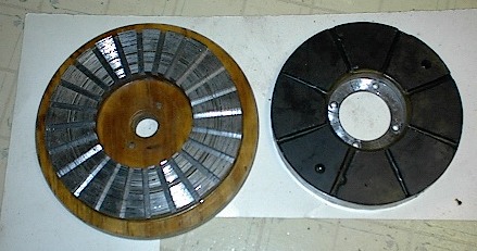
 The first pic shows the magnet used before being cut into 8 equal
sections. The next shows the stator after slotting and the magnetic disc.
The first pic shows the magnet used before being cut into 8 equal
sections. The next shows the stator after slotting and the magnetic disc.