


|
|
|
Understanding 3 phase alternators.... Three phase is nothing more than single phase with 2 extra coils slightly out of phase with first. Basically "Phase" relates to the timing of the magnets passing over the coils at different times. With single phase the magnets and coils all line up with each other and are said to be in "phase". The diagram below shows single phase wiring....
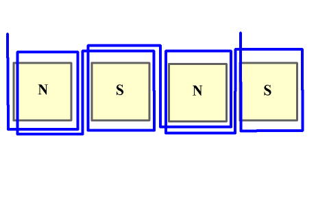
In a single phase unit the coils are wound opposite of the first. That is to say one is wound clockwise and the next is counter clockwise. If your unit has 8 magnets then it would also have 8 coils. With 3 phase you would have 3 coils for each pair of magnets. A pair meaning one north and one south magnet. There are many combinations for any one set up. For instance you could use 8 magnets and only have 6 coils without overlapping them... or 3 set of 4 coils in series. For now we won't worry about the combinations and stick with the basics. Below shows a diagram of 4 magnets with the placement of each of the coil sets...
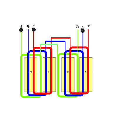
As you can see the first phase covers only the north pole magnets and are wound all in the same direction. The other of the two are identical to the first with the exception they are offset equally. The next diagram shows all the sets in place for a 4 pole alternator. You end up with 3 start wires labeled A,B,C and 3 end wires labeled D,E,F. The output wires to this arrangement would be A, C and E. The reason E is an output or ends up being a "start" wire is because when the magnet passes over the 2nd phase its out of phase between the 1 and 3 so the ends are reversed instead of winding them in the opposite order.
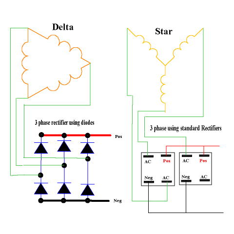
Now to connect the ends and change the AC to DC for battery charging... Below shows the star and delta symbols and 2 different types of rectifiers. Either rectifier can be used for star or delta. You can use diodes and make your own rectifier set up or you can purchase the standard rectifiers. Notice on the standard rectifiers one AC lead isn't used. Similar to the diodes, a rectifier that is already made up for such use and my personal preference is a unit from a GM alternator. They seem to give the best rectified output out of all of them. I'm not sure why but they do. They are expensive to buy new but usually you can get them from the junk yard fairly cheap. Sometimes get the whole alternator for around 15 bucks. They also make a nice clean set-up. There are basically two ways to wire a 3 phase alternator, star ( or Wye) and Delta. With Delta you get lower voltage but more amps. In star you get higher voltage but less amps. You can calculate these by using the square root of 3 ( or 1.732 ). Each coil set is a "phase" of the alternator so when you measure voltage,ohms or current to test one phase of the alternator you would measure the "phase". Once you know what the output will be from one phase you can calculate the "line" output of either delta or star. The line voltage would be measured from any 2 of the 3 outputs. If one phase measured 22 volts in your test and 10 amps then the star configuration would produce 38 volts and 10 amps ( 22 x 1.732 ). The amps remain the same as the phase measurement because the star is basically series'd to another phase. In Delta you would get 22 volts at 17.32 amps (10 amps x 1.73 ). If you calculate this out 22 volts x 17.32 = 381 watts and 38 x 10 = 380 watts... so what is the advantage? Typically the resistance in Delta is 1/3 the resistance of star. If the resistance of star was 1.5 ohms we could calculate the output ( see formula section ). Lets assume the test was at 600 rpm, we achieved 38 volts in star ( about 16 rpm per volt ) so at 1000 rpm we would get 62.5 volts less battery voltage of 12.6 = 49.9 volts / 1.5 ohms = 33.26 amps * 12.6 = 419 watts... not to bad. Now in delta we had 22 volts at the same rpm ( about 27 rpm per volt ). So at the same 1000 rpm we get 37 volts - 12.6 battery = 24.4 volts / .5 ohms = 48.8 amps * 12.6 = 614 watts. Almost a 200 watt gain !!! The advantage of star is the higher voltage at lower rpm which means our unit would have to make 201 rpm to start charging at 12.6V where the Delta would require 340 rpm to start charging.
Some Basic factoids about 3 phase.... Most of the electric power in the world is 3 phase. The concept was originally conceived by Nikola Tesla and was proven that 3 phase was far superior to single phase power. 3 phase power is typically 150% more efficient than single phase in the same power range. In a single phase unit the power falls to zero three times during each cycle, in 3 phase it never drops to zero. The power delivered to the load is the same at any instant. Also, in 3 phase the conductors need only be 75% the size of conductors for single phase for the same power output. And there you have it ! Not really much more difficult than single phase but much more efficient !!!
|